Product Description:
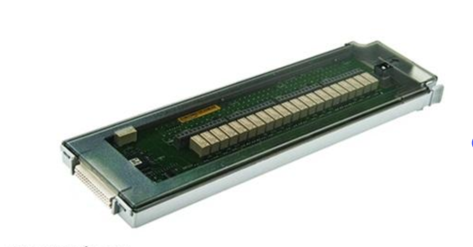
Use the Agilent 34908A to achieve maximum density in common low applications, such as cell testing, component characterization, and benchtop testing.
Each module switches 40 single-wire inputs. Supports all 2-wire internal measurements except current. The low level connection of the module is isolated from the ground, and the voltage can be floating up to 300 V.
Module Specifications Agilent 34970A Precision specifications are included in the chart
Switch offset and reference junction error as shown in. These errors are listed separately and used to determine the systematic errors of the external measurement equipment. These errors are listed separately and used to determine the systematic errors of the external measurement equipment.
Up to three modules of any combination can be inserted into a single host. The internal DMM connection of the 34970A can only be accessed through the 34901A, 34902A, and 34908A low-frequency multiplexers.
The screw terminals on the module accept wire sizes from 16 gauge to 22 gauge. For high channel count applications, line 20 is recommended. The 34905A and 34906A RF multiplexers use SMB connectors. Each RF module is supplied with a standard (10) BNC to SMB adapter cable for easy BNC connection.
Product Features:
Simulate the 34901A, 34902A, and 34908A multiplexer channels
Digital 34907A digital input and accumulation
Scan list scans channels in ascending order
Trigger of scan
Source interval, external, button press, software or monitor channel alarm
Scan counts 1 to 50,000 or continuous
Scan interval 0 to 99 hours; 1ms step size
Channel delay 0 to 60 seconds per channel; 1 millisecond step
External trigger delay <300 microseconds. Monitor on <200 ms
External trigger jitter <2 ms
Alarm
The simulated inputs Hi, Lo, or Hi + Lo are evaluated for each scan
Number input 34907A can mask numbers in pattern matches or state changes
34907A Add up: Upper limit only
Monitor channel alerts evaluate each reading
Alarm output 4 TTL compatible
TTL logic high or low can be selected in case of failure
5 ms delay (typical value)
Memory
Battery powered, typical life of 4 years 1
50,000 time-stamped readings
Readable during scanning
State 5 instrument states with user labels
The alarm queue has a maximum of 20 events, including channel numbers, readings, and timestamps
Characteristics of the system
Each channel math separate Mx + B scaling and real-time calculation of the minimum/maximum/average