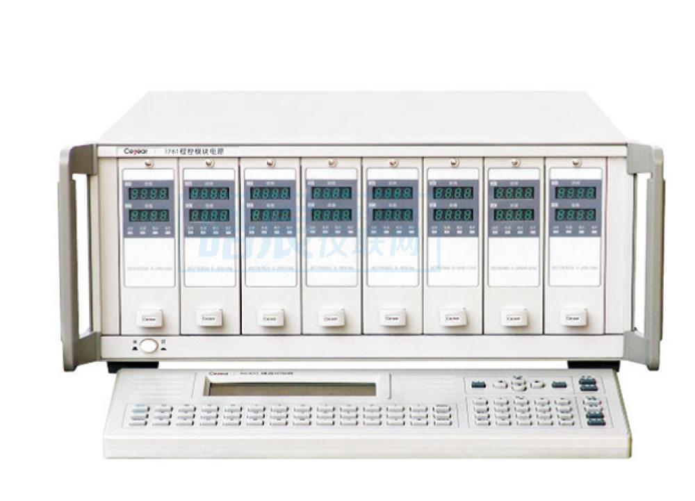
Product Description:
The 1761 programmable module power supply is an ideal device for providing bias power and stimulating components or final products in an automatic test environment. It is an essential test instrument for test systems. It is suitable for automatic testing fields such as R&D, design, production and manufacturing.
The 1761 program-controlled module power supply provides flexibility for users to select power supplies. 1 to 8 (or customized) modules can be purchased according to their needs. Each module can work in series and parallel; and two mainframes can be cascaded to achieve up to 16 output, the total output power can be extended to 3200W. Its sequence output function allows you to set 20 groups of voltage, current and dwell time for each output. Overvoltage and overcurrent protection points can be set by yourself. Isolation and polarity reversal options can disconnect the positive and negative poles of the power output, and can reverse the positive and negative poles. The interface standard configuration is GPIB, and the program control commands are fully compatible with the industry standard SCPI command set. 1761 program-controlled module power supply also has lower voltage and current ripple and noise, and its noise index has reached the standard of high-quality linear power supply.
Main feature:
-
High power density mainframe (0~1600W), 8 standard modules for easy selection: single module output 150W or 200W, purchase multiple modules to form a multi-output power supply system, a single mainframe can be equipped with up to 8 modules (200W×8= 1600W), special requirements can be customized
-
Built-in serial link function enables two hosts to control up to 16 outputs with one GPIB address
-
Programmable fixed voltage (or current) output, and can also set voltage and current output sequences (that is, program multi-point voltage and current that change with time or events)
-
Modules can be reconfigured in series or parallel to expand the output voltage and current range
-
Excellent performance indicators: high-precision programming and readback measurement, pure and low-noise output
-
Multiple sets of settings are stored
-
Complete protection functions: overvoltage, overcurrent, overtemperature protection
-
Isolation and Polarity Inversion (Option)
-
Unique connector assembly for simplified system integration
-
Local/remote detection function
-
GPIB (IEEE 488.2) interface control, optional 86402 keyboard controller (option) to simplify operation
Typical application:
-
Local/remote detection
-
Local detection is selected, and the feedback of the power supply is taken from the output terminal on the output connector. This method ignores the loss of the voltage drop of the load line and limits the adjustment ability of the power supply. The longer the load lead and the greater the resistance, the adjustment ability of the terminal load will be reduced. The worse it is, it is suitable for occasions that do not require high load regulation rate. Remote detection is selected, the feedback of the power supply is directly taken from the load, and the output of the power supply voltage automatically compensates for the influence of the load lead, so that the voltage on the load remains unchanged.
-
When remote detection is selected, if the load voltage is at the rated value, the actual output voltage of the module may exceed its maximum output range, which will cause the protection circuit to operate or output imbalance. When remote sensing is selected, the noise picked up on the module output by the sense lines will affect the load regulation. In order to minimize the impact of noise, shielded twisted pair should be used to connect the detection line of the power supply to the voltage detection terminal of the load, one end of the shielding layer should be connected to the ground terminal of the output connector of the power supply, and the other end should be left floating, and the shielding layer should not be used. as a detection line.
-
The selection switch of local detection and remote detection is set on the output connector, and the factory setting is "local detection". When local detection is selected, connect as shown in figure a); when remote detection is selected, connect as shown in figure b).
-
Parallel output
-
Using two or more modules in parallel can expand the current output range. But the following settings are required: set one module to work in constant voltage (CV) mode, and other modules in constant current (CC) mode, the output programming voltage value of the constant current module should be higher than the constant voltage module, and the load current must be large enough In order to make the constant current module in the constant current working mode. If remote detection is used, the detection line should be connected to the constant voltage module. The figure below shows how to connect two modules in parallel. When outputting in parallel, try to make the output power of each module the same.
-
series output
-
Using two or more modules in series can expand the voltage output range. However, it should be noted that the load current should not exceed the current output range of each module, and the load voltage should never exceed the module's floating voltage rating (320V). If the output is a capacitive load, such as a battery or a large capacitor, it should be synchronized when the module is turned off. Otherwise, when one of the modules is turned off, the voltage on the load will exceed the output withstand voltage range of the single module, resulting in module damage. The diagram below shows how two modules are connected in series.


 服务热线:0755-86016691 电话:13715327187 传真:0755-86641139-816